pgmfi.org

Hacking up Honda's ECU
It is currently Wed May 22, 2024 2:40 pm

All times are UTC - 5 hours [ DST ]


Post new topic Reply to topic  [ 59 posts ]  Go to page 1, 2, 3, 4  Next
Author Message
PostPosted: Fri Feb 16, 2007 1:07 pm 
Offline

Joined: Tue Jul 27, 2004 2:10 am
Posts: 833
Location: Running in illogical circles
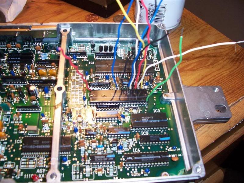
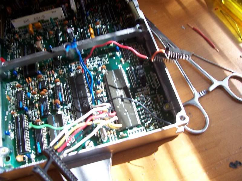
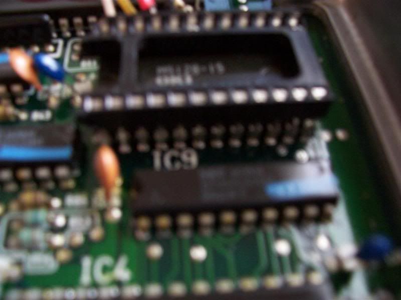
Good day! I am attempting to chip a ROMless 88 PM6 following the guide in the WiKi and the several threads that have been produced on the subject. I think I dun screwed up already. heh Here is what I have got so far!

Image
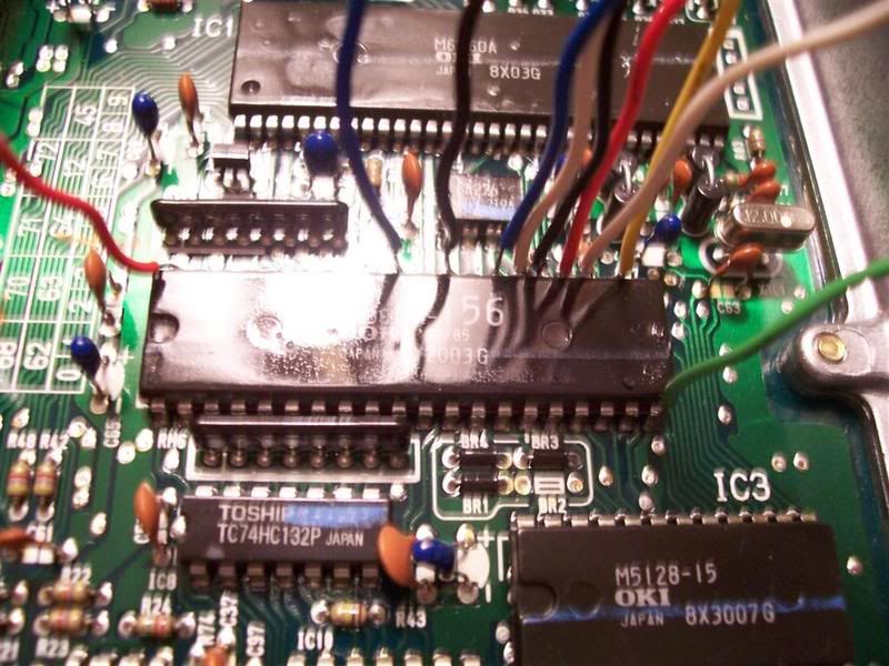
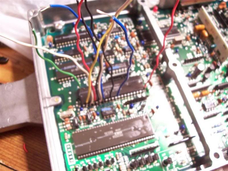
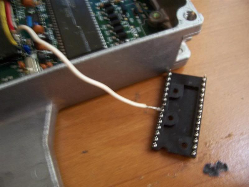
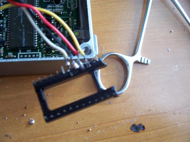
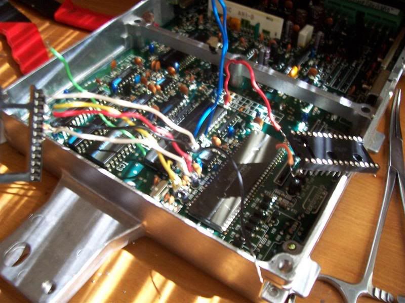
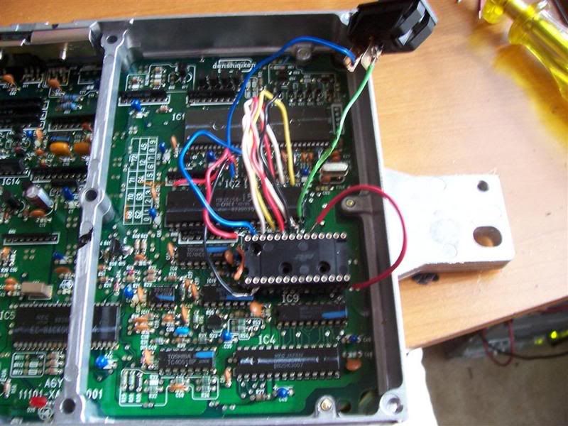
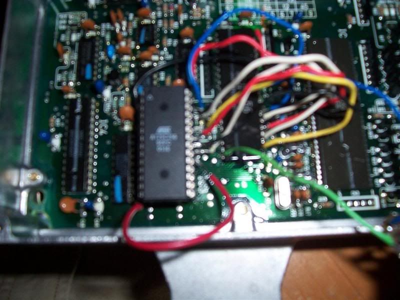
As you can see in the pic above, I have the EPROM in there already, and yes, I know it's not correct yet. I just put it in there to make sure I didn't screw anything up with my (poor) soldering skills. (I can solder stuff onto boards, I just have never used solder to stick stuff to the outside of anything like this before.) Now, what I am most ly concerned with is that I think that I shouldn't have soldered ALL those legs to the chip below. The pics that have been posted previously by others doing this are not at all helpfull to me. If anyone would want to contribute better photos of how they've done this, please do. That would be of great help to me and the community at large.

Image

Image

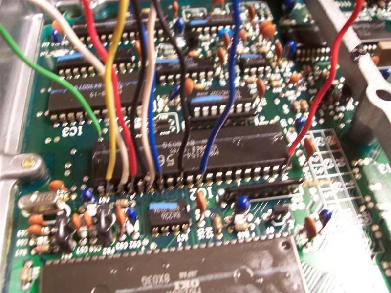
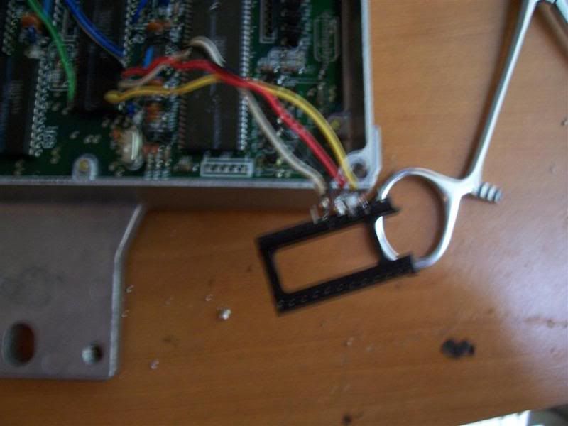
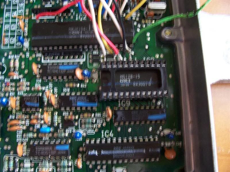
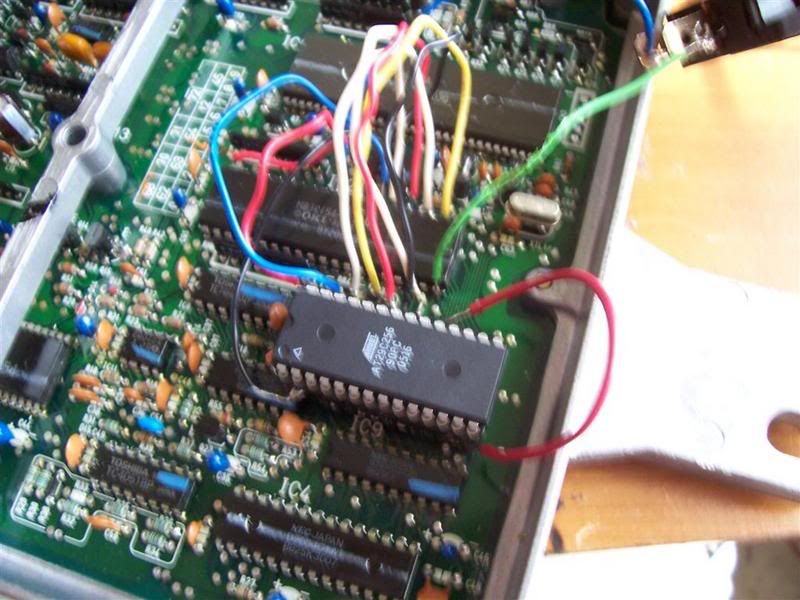
Do I have the wires soldered to the correct legs of this chip? It was rather difficult to tell from the previous pictures, as again, they were not clear or at the right angle to tell what went where. The only reason there are two different size wires is that I had different wire widths available.

If anyone would care to comment on my soldering or give me points as to how to make this type of better, or if, miraculously, they are fine, I would appreciate that, too.

Pics hosted courtesy of The ZC Resource.


Top
 Profile  
Reply with quote  
 Post subject:
PostPosted: Sat Feb 17, 2007 4:05 pm 
Offline

Joined: Tue Oct 31, 2006 1:44 pm
Posts: 19
Location: Slovenia
You connected your EEPROM totally wrong. You connected it directly :shock:
http://www.pgmfi.org/twiki/pub/Library/ ... C00667.jpg

Please read the wiki carefully and take a look at the pictures :!:
http://www.pgmfi.org/twiki/bin/view/Lib ... An88-89ECU Connect according to the last(second) table!

Check this thread also: viewtopic.php?t=953[/url]

I successfully chipped my PM6 today 8)


Top
 Profile  
Reply with quote  
 Post subject:
PostPosted: Sun Feb 18, 2007 1:53 am 
Offline

Joined: Tue Jul 27, 2004 2:10 am
Posts: 833
Location: Running in illogical circles
*sighs* I know the chip isn't supposed to be there. I just had it there to make sure that when I soldered the socket on, I didn't screw up the spacing or anything because I had never soldered anything like that before.

I have been through those threads and the WiKi. The pics in the threads are not focused or from angles that don't help me. The chart in the WiKi is also fairly useless to me as I don't have a freaking clue as to what pin is what. I am asking for better pics as I am a better visual learner!

I am asking for better pictures or a decent idiot-proof schematic of some sorts for my retarded, n00b mind to graps WTF is supposed to go where!


Top
 Profile  
Reply with quote  
 Post subject:
PostPosted: Sun Feb 18, 2007 5:45 am 
Offline

Joined: Sat Oct 02, 2004 11:02 am
Posts: 379
here ya go beave...lucky i took a bunch of pictures when i did a pg7. i used the guide in the wiki and i also used just what little stuff i had. very messy and obviously can be done cleaner but between this and the wiki you might be able to get it done.

Image
Image
Image
Image
Image
Image
Image
Image
Image
Image
Image
Image
Image
Image
Image
Image


Top
 Profile  
Reply with quote  
 Post subject: Chipping
PostPosted: Sun Feb 18, 2007 7:24 am 
Offline

Joined: Tue Oct 31, 2006 1:44 pm
Posts: 19
Location: Slovenia
Some more photos, just to make it clear :)
Note that there are two(2) sockets used for chipping, because the EEPROM is not fully connected to the External RAM chip :!:
Man, I hope you don't chip your ECU only according the photos.
The table(second) in the wiki is perfect IF you know in what way are the pins numbered.

I also did a complete simple wiring scheme for you, I hope you like it 8)


You do not have the required permissions to view the files attached to this post.


Top
 Profile  
Reply with quote  
PostPosted: Sat Apr 04, 2009 10:00 pm 
Offline

Joined: Tue Aug 01, 2006 4:53 am
Posts: 291
Location: Auckland, New Zealand
Can someone please confirm whether this method can be used with the SST27SF512 Eeprom?


Top
 Profile  
Reply with quote  
PostPosted: Sun Apr 05, 2009 12:32 pm 
Offline

Joined: Sat Jul 16, 2005 12:43 am
Posts: 112
wow that looks like a ton of work just for a chipped ecu.


Top
 Profile  
Reply with quote  
PostPosted: Sun Apr 05, 2009 10:07 pm 
Offline

Joined: Tue Aug 01, 2006 4:53 am
Posts: 291
Location: Auckland, New Zealand
It's not vard or time consuming if you get it right. If you put a wire in the wrong place then it becomes time-consuming to figure out your muckup . . .

Now back to my original question.

Can this setup be used with an sst27sf512 chip? The pinouts are nearly identical except for pin 22 on the 512k.

See picture for reference.


You do not have the required permissions to view the files attached to this post.


Top
 Profile  
Reply with quote  
PostPosted: Sun Apr 05, 2009 10:47 pm 
Offline

Joined: Sat Jul 16, 2005 12:43 am
Posts: 112
shiftyjonno wrote:
It's not vard or time consuming if you get it right. If you put a wire in the wrong place then it becomes time-consuming to figure out your muckup . . .

Now back to my original question.

Can this setup be used with an sst27sf512 chip? The pinouts are nearly identical except for pin 22 on the 512k.

See picture for reference.


nice pinout for chips.


Last edited by dohcef8si on Mon Apr 06, 2009 7:21 am, edited 2 times in total.

Top
 Profile  
Reply with quote  
PostPosted: Mon Apr 06, 2009 3:50 am 
Offline

Joined: Tue Aug 01, 2006 4:53 am
Posts: 291
Location: Auckland, New Zealand
Now back to my original question.

Can this setup be used with an sst27sf512 chip? The pinouts are nearly identical except for pin 22 on the 512k.


Top
 Profile  
Reply with quote  
PostPosted: Mon May 04, 2009 2:39 am 
Offline

Joined: Mon Mar 23, 2009 5:11 am
Posts: 15
shiftyjonno wrote:
Now back to my original question.

Can this setup be used with an sst27sf512 chip? The pinouts are nearly identical except for pin 22 on the 512k.


Yes, but you must take care with pinout order, and if you want to have 2 maps on same chip, you can connect one switch with 5v supply to pin 22 and have 0-255 addressing and 256-512 addressing !!

I'm chipping an pm7 romless too, but i want to go RTP (Real Time Programable) way.

I must do this schema to made EEPROM adapter and then the other RTP circuit with 27Cx emulation?

Or i can do another direct reemplacement without romadaptor ?

Thanks!


Top
 Profile  
Reply with quote  
PostPosted: Mon May 04, 2009 1:39 pm 
Offline

Joined: Tue Aug 01, 2006 4:53 am
Posts: 291
Location: Auckland, New Zealand
Thanks for your reply alecuba16

Right, Last night I had a go at chipping a romless ECU with 2 maps on an sst27sf512 using 'mynameistin's' method. I had previously been using the 'daughterboard' style adapter, but found it to bee a little bulky.

Success with 2 maps on a 512k chip has been a bit scarce . . . I think the 4.7k resistor I was using was a little too high and so I've switched to using a 1k resistor. I'll test it out later today and post the results and a couple iof pics.

So theoretically I should now have 3 maps (2 on the chip, and then the stock map).

Quote:
I must do this schema to made EEPROM adapter and then the other RTP circuit with 27Cx emulation?

Or i can do another direct reemplacement without romadaptor ?


Which RTP board/design are you using?

Personally, I was looking at removing the bulky plastic cover from my Ostrich 1 and mounting the board in the ECU itself. In a permanent arrangement.


Last edited by shiftyjonno on Tue May 05, 2009 1:19 pm, edited 1 time in total.

Top
 Profile  
Reply with quote  
PostPosted: Mon May 04, 2009 7:46 pm 
Offline

Joined: Mon Sep 15, 2008 8:11 pm
Posts: 24
i have a feeling you may be switching the wrong pin should be like this and with 4.7k or 10k resistors i wouldnt myself go any lower or higher.you need to pull pin 1 out of the socket so its not getting power from the socket only accross the resistor.heres a pic off our delco ecu website.


You do not have the required permissions to view the files attached to this post.


Top
 Profile  
Reply with quote  
PostPosted: Mon May 04, 2009 7:57 pm 
Offline

Joined: Tue Aug 01, 2006 4:53 am
Posts: 291
Location: Auckland, New Zealand
:Stumped:

I fully understand that pin 1 of the EEPROM must be disconnected from the PCB.

Thats how i've always been doing it, (with 4.7k and sometimes 10k resistors) but its only worked on a couple of ECU's . . . . I'm stumped as to why.

I've got a bit of time to have a muck around on it tonight, so hopefully i'll sort it out.


Top
 Profile  
Reply with quote  
PostPosted: Tue May 05, 2009 1:17 pm 
Offline

Joined: Tue Aug 01, 2006 4:53 am
Posts: 291
Location: Auckland, New Zealand
Success!

Last night I was testing the 2 rom map on an 88 Romless ECU. I used the 'double socket' method as opposed to the daughterboard style which I had previously been using.

Before I started, I checked and rechecked that my soldering was good . . . (it always is!!)

1. First, I used a 1k resistor and got a solid CEL.
2. I then swapped the 1k resistor for a 4.7k resisitor and got a solid CEL.
3. I then swapped the 4.7k resistor for a 10k resistor and STILL got a solid CEL.
4. After rechecking that the soldering and hardware were setup correctly, I figured that the last thing I could check would be the chip itself.
5. I reprogrammed the sst27sf512 chip with the dual map (64kb) file.
6. SUCCESS!! . . . It worked like a charm.

It was then possible to switch between stock and 2 rom maps with no issues.

CONCLUSION:
I figure that when I first tested out the dual map with a 1K resistor, that I might have somehow mucked the program up. After erasing the chip a couple of times, and then re-programming the 64kb bin file (on the SAME chip) everything went fine.


Top
 Profile  
Reply with quote  
Display posts from previous:  Sort by  
Post new topic Reply to topic  [ 59 posts ]  Go to page 1, 2, 3, 4  Next

All times are UTC - 5 hours [ DST ]


Who is online

Users browsing this forum: No registered users and 27 guests


You cannot post new topics in this forum
You cannot reply to topics in this forum
You cannot edit your posts in this forum
You cannot delete your posts in this forum
You cannot post attachments in this forum

Search for:
Jump to:  
Powered by phpBB® Forum Software © phpBB Group